It's a great joy at home if the car doesn't disappear through the garage door that was left open all night, the apartment isn't broken into, and criminals don't break in on the people sleeping inside.
Leaving it open could not have happened if the delayed automatic closing function had been set on the control of the otherwise motorized garage door - which, for reasons of practicality, e.g. unloading from the trunk towards the other entrance, - had not been set. However, it could easily be set, since it would indicate in advance if it wants to close because the time has come.
An external light can be connected to most of the controls of gate or garage door operators, which first lights up continuously when the gate is open, and then starts flashing after a while, indicating that the gate will automatically move towards its next stop. This simple form of feedback can be said to be typical and clear not only for gate movement but also for other operational processes.
Even with the quiz game controls discussed in previous letters, it could be used well to indicate thinking time. For example, a continuous signal can mean the start of the thinking time and an intermittent, flashing signal that the end is approaching. In the following, we will look at some light signal solution options with relays (and then also triacs), from the simplest to the more tricky ones.
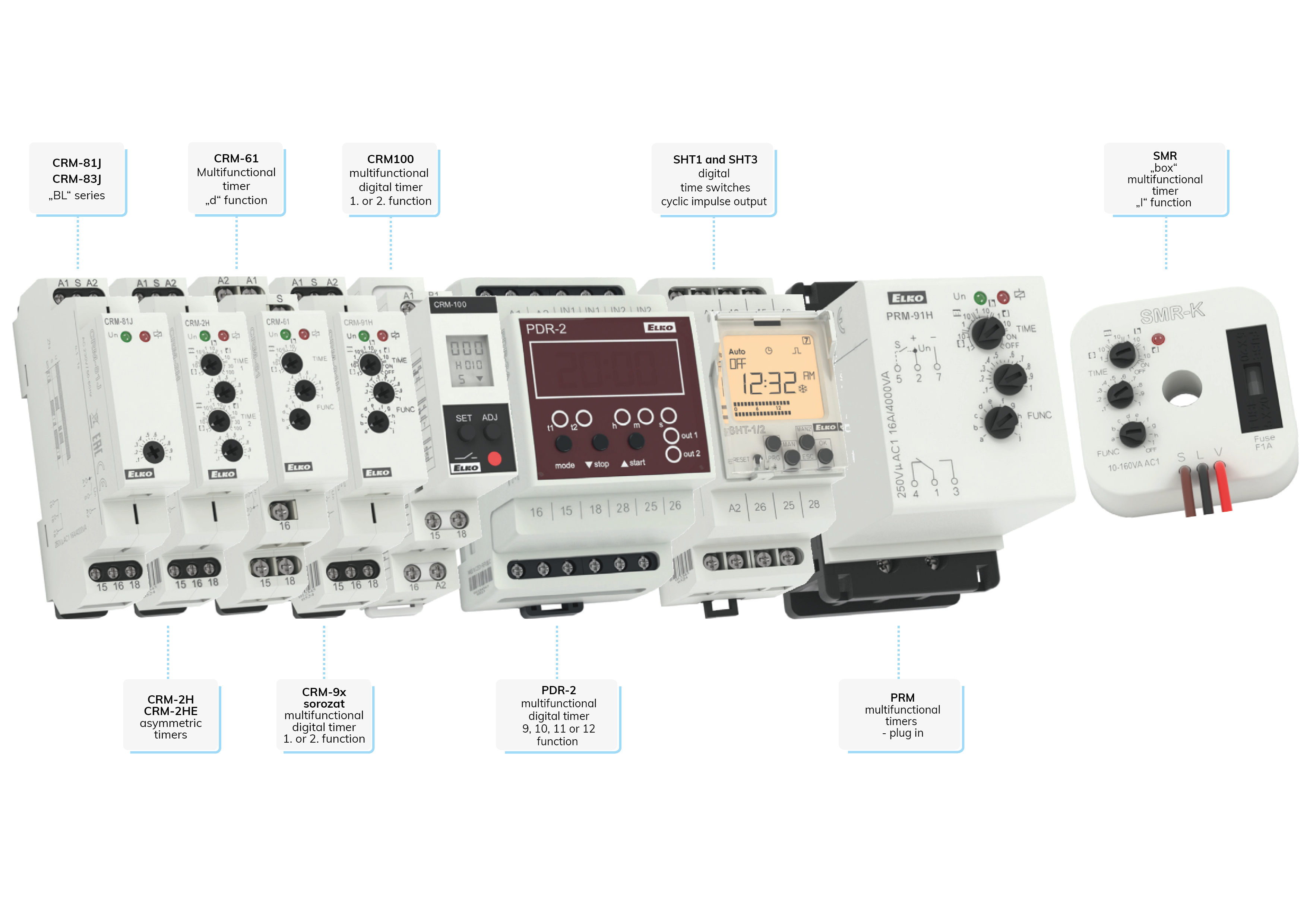
Some of ELKO EP's special and multi-functional time relays are pre-configured with this timing function, so in the simplest case, all we have to do is set this function and the light can start flashing. Although with more limited time values (1 - 99 seconds), some digital switch clocks also contain a programmable timing function. Figure 1 shows the ELKO EP timing devices that also have a timing function (see the RELAY product group).
The scheduling of most time relays can be started by switching on the power supply, if it is set to this function (or already does this), but e.g. with the SMR types, all functions can be started with a START signal with a constant power supply, including the timing.
With normal time relays, only one-time variables can be set, therefore, in the timing function, the durations of switching the output on and off will be the same (symmetric timing transmitters). This differs from time relays with an asymmetric timing function, where the pulse and pause duration can be set separately. Operating diagrams of the timing functions of each device can be found in the downloadable user guides.
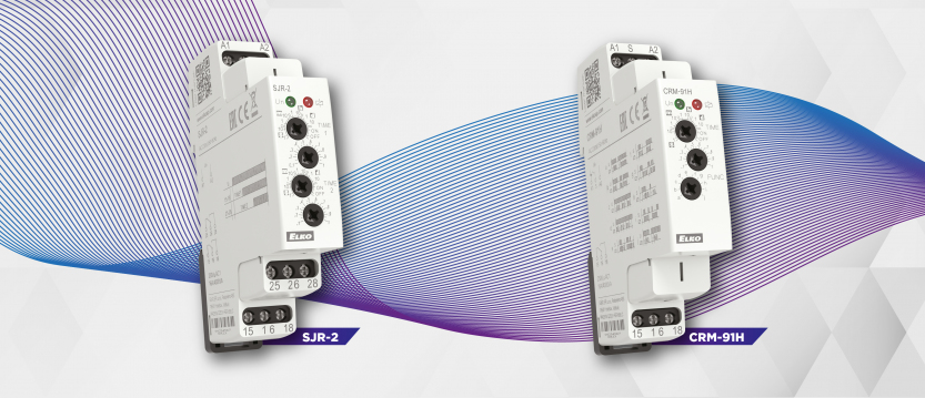
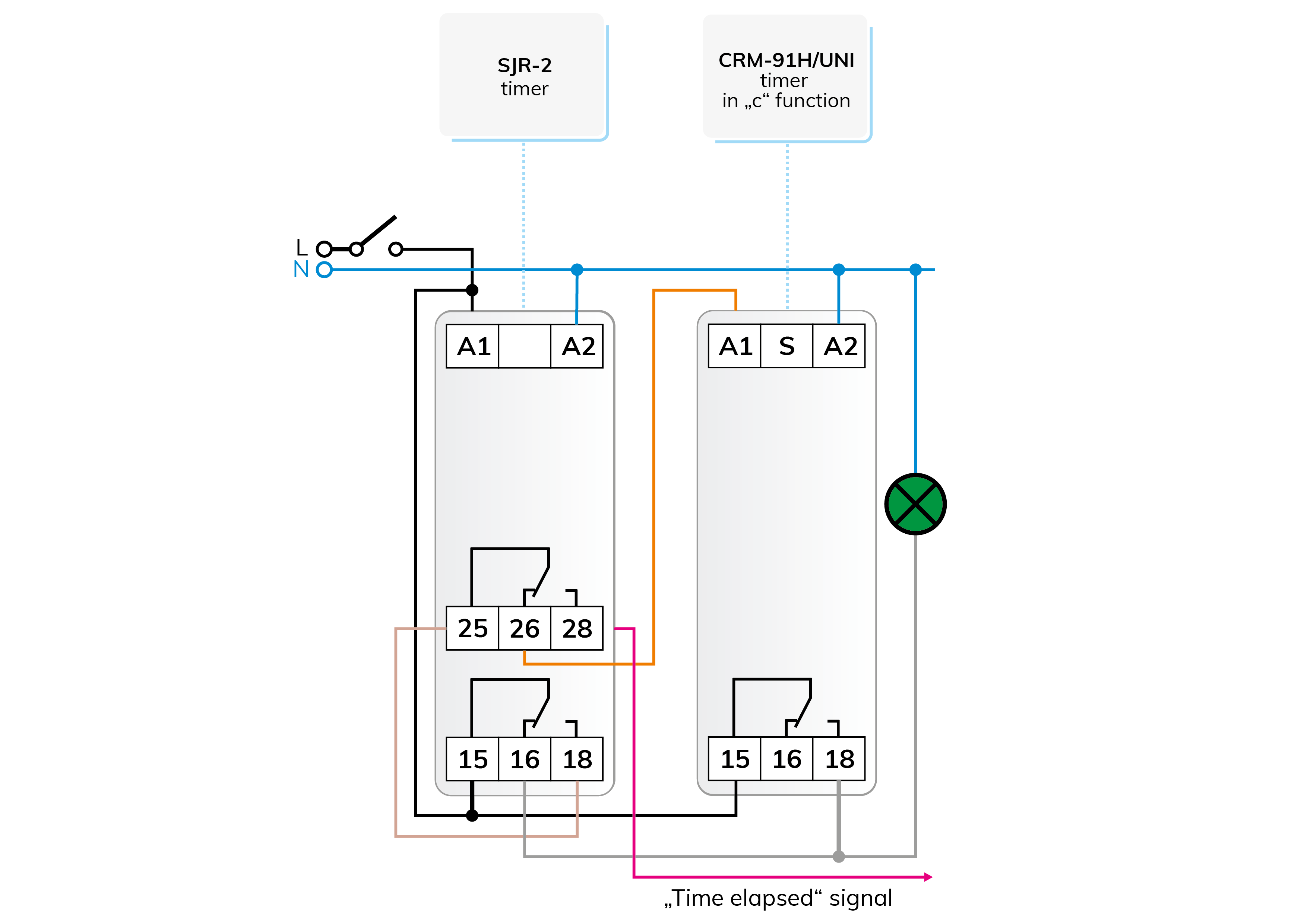
Regarding to the already presented quiz game topic, we can signal the passage of time to the players with the connection shown in Figure 2. The countdown of the thinking time starts with the continuous lighting of the signal light, and before the end, a light that flashes for a predetermined period indicates that the time is about to expire and an answer must be given.
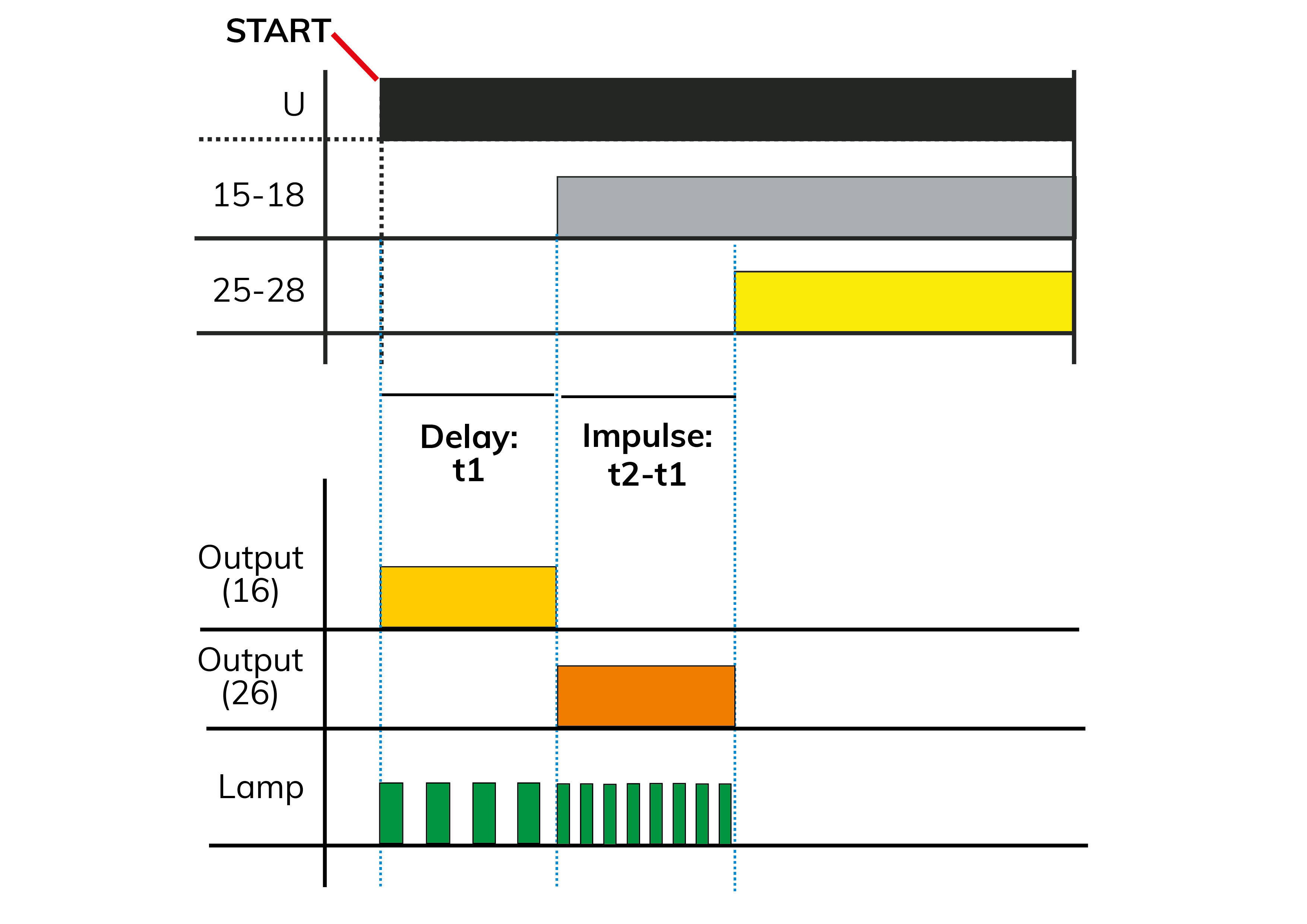
The operation is also illustrated in the diagram in Figure 3.
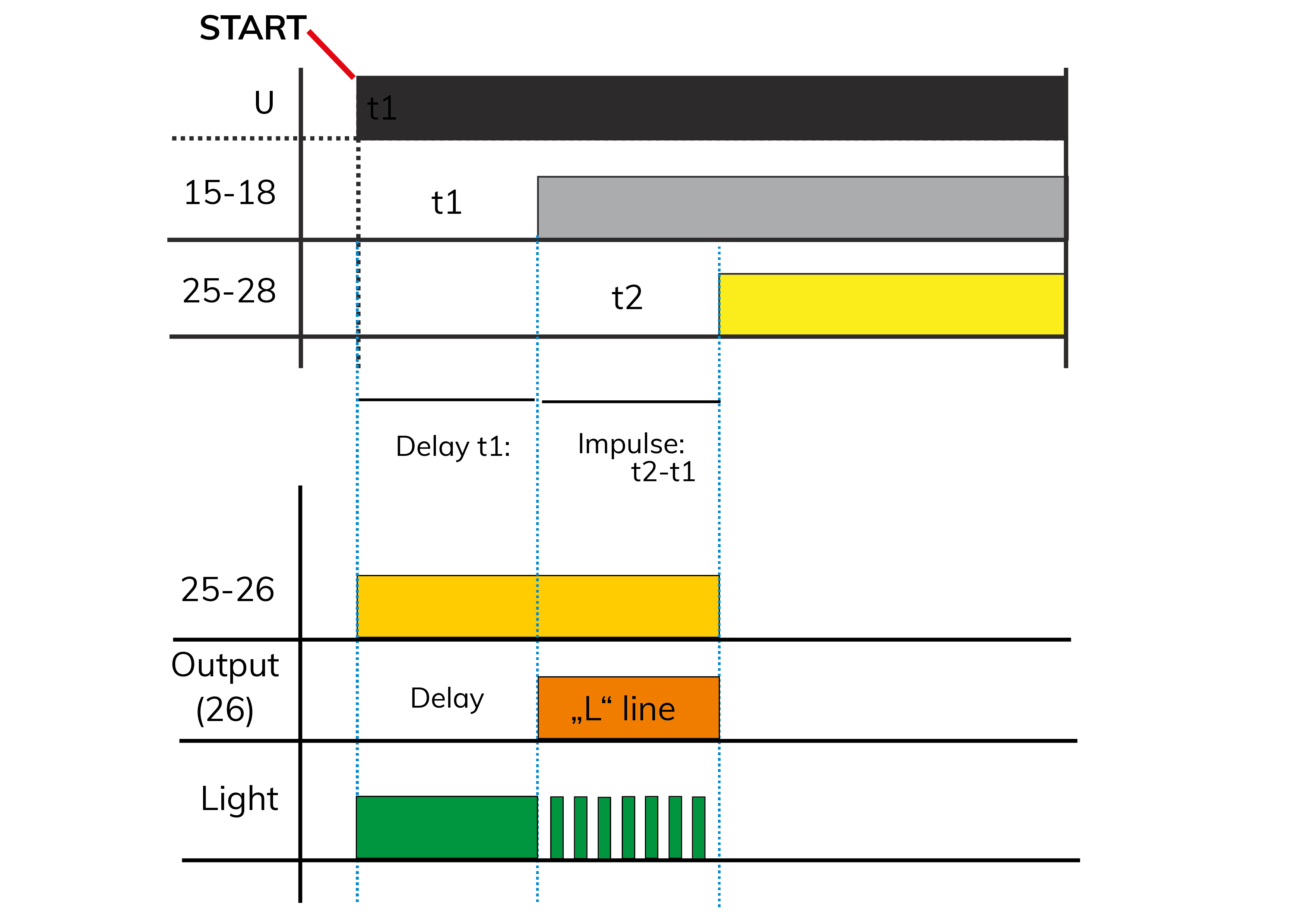
The rest of contact 16 of channel 1 of the special time relay SJR-2 ensures continuous lighting of the indicator lamp until time "t1" elapses. Then contacts 15 - 16 break and the phase connected to output 18 is also received by terminal 25 of channel 2.
The phase connected to idle contact 26 provides power to the CRM-91H time relay. The time relay is set to the timing function that starts on the supply voltage, so its output will flash the indicator lamp for t2 - t1, then contact 25 - 26 will break, which will disconnect the indicator lamp. The connection of the phase to terminal 28 may indicate the expiration of the time. Restart by turning the power off and then on.
Another CRM-91H time relay can be used instead of the SJR-2, but then the indication of the end of the time (wire indicated by an arrow) must be solved differently, possibly by installing an additional relay, which increases the cost and the size of the circuit. The first-time relay can be a release or tightening delay, but of course, the wiring must be modified accordingly.
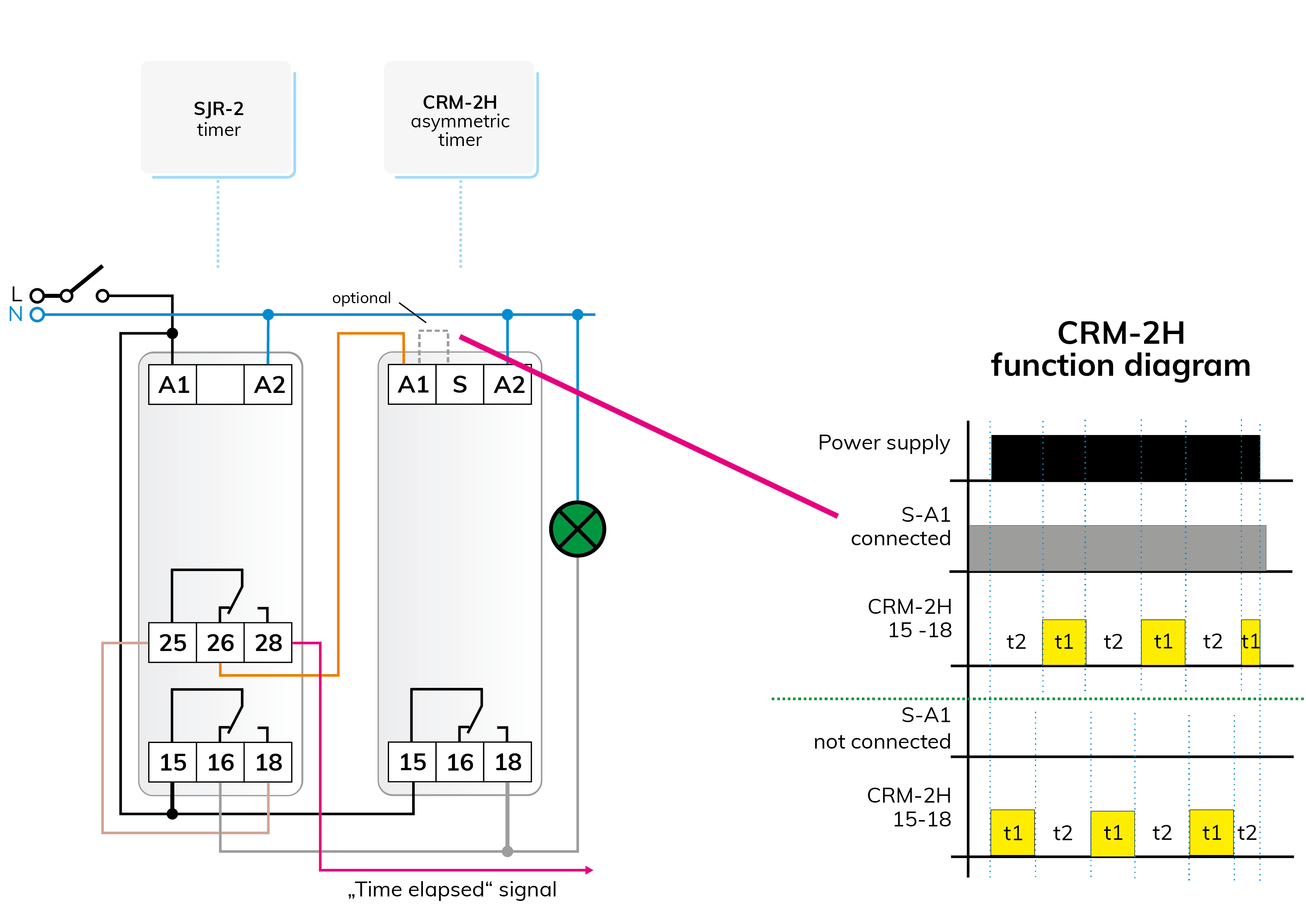
To convert the flashing part of the basic circuit discussed in the previous section to an asymmetric one, we only need to replace the CRM-91H time relay with the CRM-2H type asymmetric timer. Thanks to the replacement, we can freely choose the pulse and pause durations of the output between 0.1 sec and 100 days (!) separately (2x2 pots are available for setting), in this way can be set, e.g. longer light and shorter dark light flashes or vice versa. The connection is shown in Figure 4, where, as a reminder, we have also drawn the process diagram of the CRM-2H's two operating modes starting with a pause or a pulse. For the mode starting with a pause, the terminals A1 - S must be connected.
It can be even more exciting with a more spectacular light signal, e.g. a contest. By changing the continuously lit first cycle of the basic circuit to a slower flashing one, we can get a more attention-grabbing light signal, which e.g. it can draw attention to the operation of a machine, or it can bring the players of the competition who are currently thinking into a slightly more stressful state, making it difficult to concentrate. The circuit diagram is shown in Figure 5, the operation diagram is shown in Figure 6.
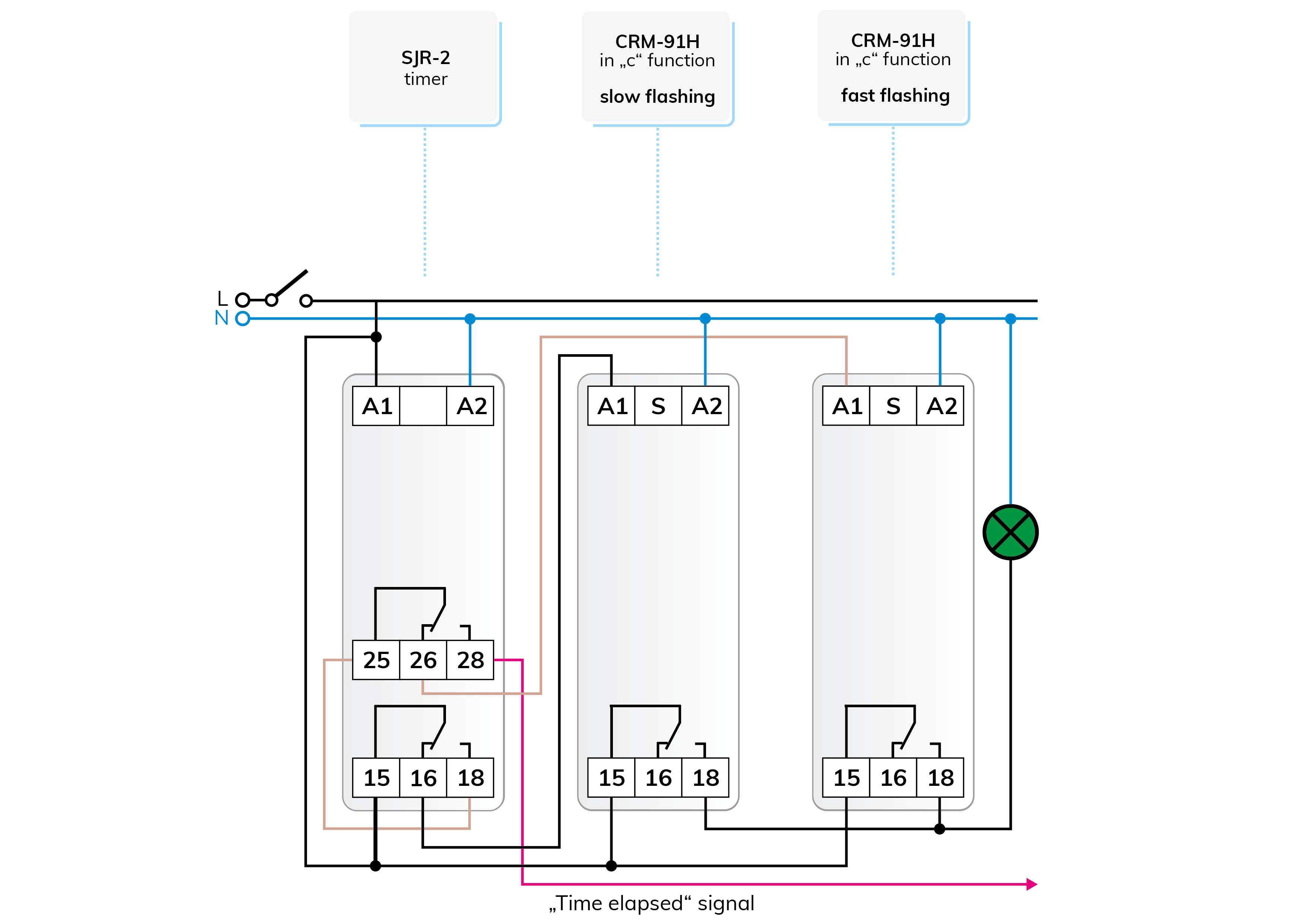
The only change in the connection compared to the basic circuit is that keeping the fast signal before the time has elapsed, controlled from terminal 25 of the SJR-2, we supplemented it with another CRM-91H time relay, on which we set a slower schedule to indicate the running of the thinking time. The outputs of the two CRM-91H are connected in parallel, and the currently active one switches the indicator light. The spectacle can be further enhanced if, instead of the parallel output, the time relays flashlights of different colors.
Let's face it, flashing with relays is not the best, even though e.g. multifunctional time relays with actual relay output may have this function from the factory. It is against using it for frequent switching that the relay has several moving mechanical parts, the switching is done by the contacts' patties and it even has a sound. The relays built into the control modules of ELKO EP are very durable, they have a relatively high electrical and mechanical service life, so in well-chosen applications, they will withstand more frequent switching on and off without any problems.
A well-chosen application means a use that is less frequently used and does not require constant, year-round "clicking" of the contacts.
However, ELKO has devices for which frequent switching is not a problem at all! One of its representatives is the CRM-9S multifunctional time relay with a modular design, which is not a relay and its 10 functions are the same as the functions of the other CRM-9x series. The output of the CRM-9S is a semiconductor electronic component, specifically a triac, the switching of which is completely silent and has no burn-in contacts (of course, this can also be destroyed). It is well-known about - especially older - dimmers, where the controlling component of the front-cutting (rising edge) phase-splitting control is the triac. The CRM-9S time relay cannot be used for regulation, but for turning on and off AC consumers. An interesting and important feature is the wide 12 - 240 V AC (50/60 Hz) supply voltage range.
Primarily suitable for switching resistive (R - ohmic) and inductive (L) loads, with a nominal current of 0.7 A. Capacitive (C) loads, such as most 230V LED light sources are not recommended to be used not only for switching but also for regulation (unless the usability is marked on the LED at the factory).
Fig. 7 shows the flashing circuit assembled with the CRM-9S time relay, which does not differ much from our usual basic circuit in its operational logic.
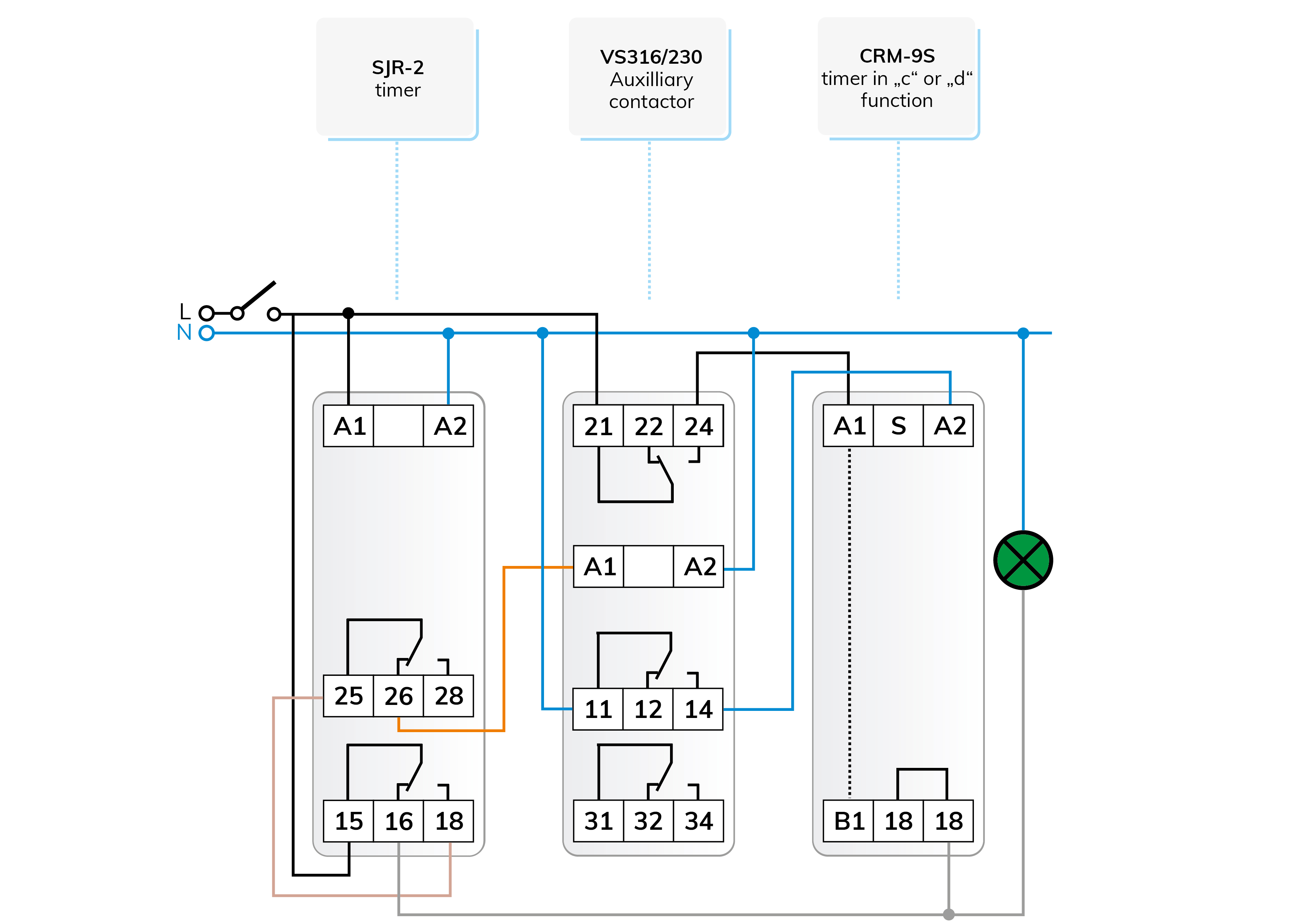
The triac located in the module connects the potential of the module's supply input "A1" to the load, that is, one anode of the triac is fixed to this potential point in the internal circuit (by the way, "A1" is also connected to terminal "B1" in the internal circuit).
The triac output and the rest (16) contact of the first channel of the SJR-2 are connected in parallel to the consumer, which does not cause problems, since the triac circuit does not even receive power when the relay switches a phase to the lamp. To avoid affecting the internal circuit of the triac, both power supplies of the module are interrupted with an auxiliary relay for the time that the relay switches a phase to the consumer (also to one anode of the triac).
If it is necessary to modify the connection for an application different from the diagram, then it is advisable to take into account that the side of the triac circuits above the load cannot be broken with impunity because the high voltage generated during disconnecting can destroy the semiconductor - this is also true for dimmers! So let's not think about this kind of modification.
The slower/faster flashing switch with asymmetric time setting, which is presented in Figure 8, was created just as an interesting feature.
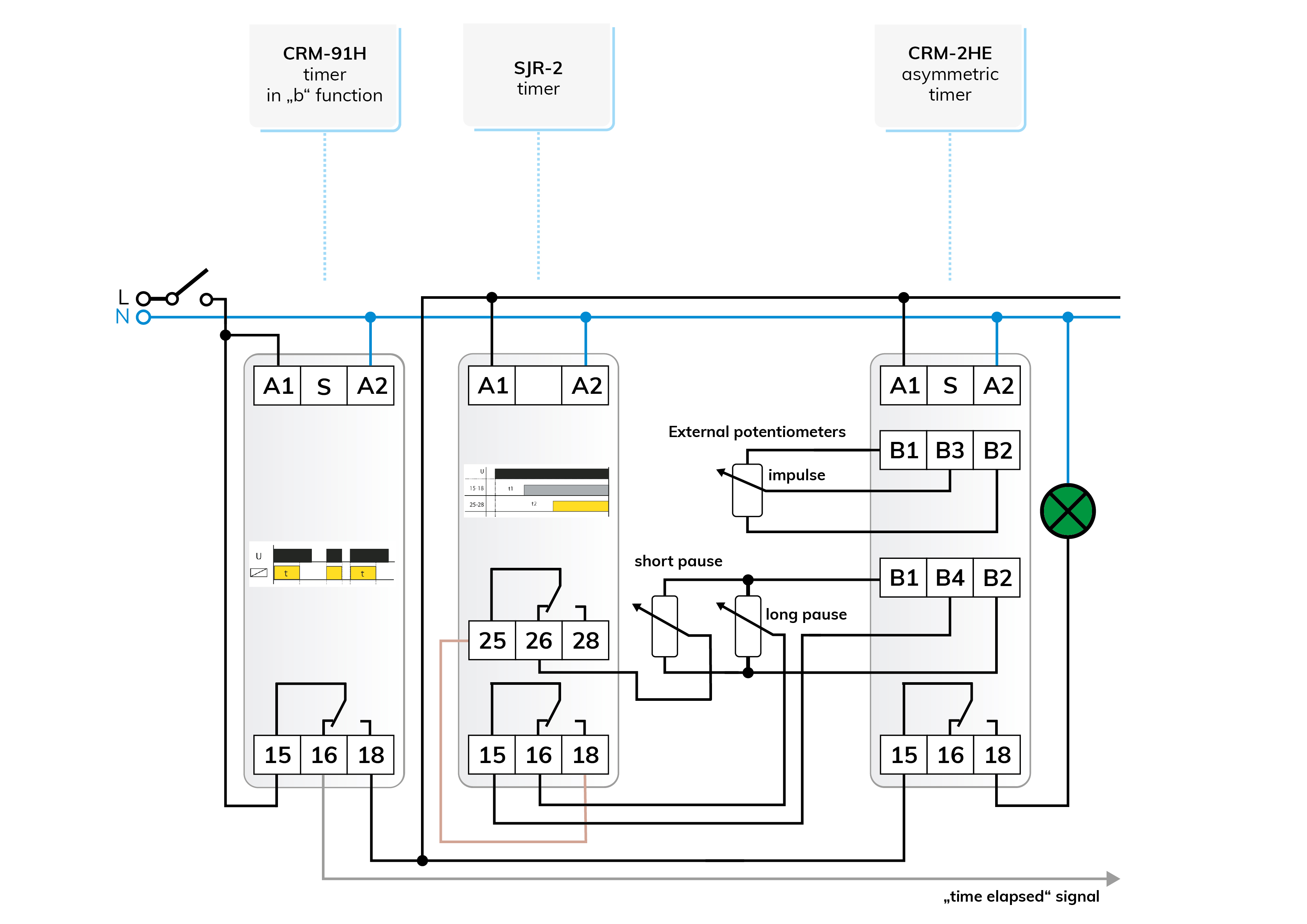
CRM-2HE type asymmetrical fine time adjustments are made with external potentiometers. Taking advantage of this, we can change the flashing speed by connecting one potentiometer to the pulse time setting and two potentiometers to the pause time setting, one of the latter being set to a longer time and the other to a shorter time.
When starting the process, the middle output of the potentiometer set for a longer pause is connected to the circuit, as a result of which the flashing appears slower. After the "t1" time of the SJR-2 has expired, we switch to the shorter pot, which will give faster flashing.
The duration of the release delay of the CRM-91H time relay determines the total operating time, and after the time has elapsed, it disconnects the flashing modules from the power supply.
The latter is necessary because contact 26 of the SJR-2 opens after the time t2 has elapsed, so none of the "pause pots" will connect to the timer. That is why it is advisable to adjust the timings so that the duration of the CRM-91H and the "t2" duration of the SJR-2 are the same as possible.
Attention! The solutions presented in the articles are illustrated with schematic circuit diagrams, which may contain errors despite repeated checks or tests under workshop conditions. It is the duty and responsibility of the installer to check and possibly modify their suitability for a given task! The author and the company assume no responsibility for damages and other problems resulting from the use of the presented principle solutions.

 E-shop