In our previous correspondences, we have addressed the issue of protection against accidental activation. Recently, we experimented with varying the duration of button presses, prompting consideration of newer, potentially more interesting, or even simpler alternatives. These are now presented in the following circuit diagrams.
The circuit diagram depicted in Figure 1 may seem familiar from a previous explanation. However, the distinction lies in the fact that the time relay function of the CRM-91H / 230V (or UNI) is initiated not from the "S" input, but by turning on the power supply. This offers the advantage of eliminating the need for a separate control cable, allowing the CRM-161 to utilize the same "a" function.
The operation can also be clearly understood from the diagram. The function of the time relay "a" is to delay the switch-on process, which begins with a simple supply voltage. When the START button is pressed, the time relay is activated, initiating the delay timer. During this delay period, the output relay remains inactive.
The duration "t" can vary, for example, between 1.5 to 2 seconds, which is generally suitable for distinguishing between short and long button presses. However, depending on the application (short button presses are not used here), it can be set to a longer duration.
The operation is as follows:
Using the time relay with the CRM-93H 3x CO contact, the self-sustaining and the output switching can be separated if necessary (e.g., different supply and consumer voltages). The circuit is depicted in Figure 2, and its operation does not require any special explanation
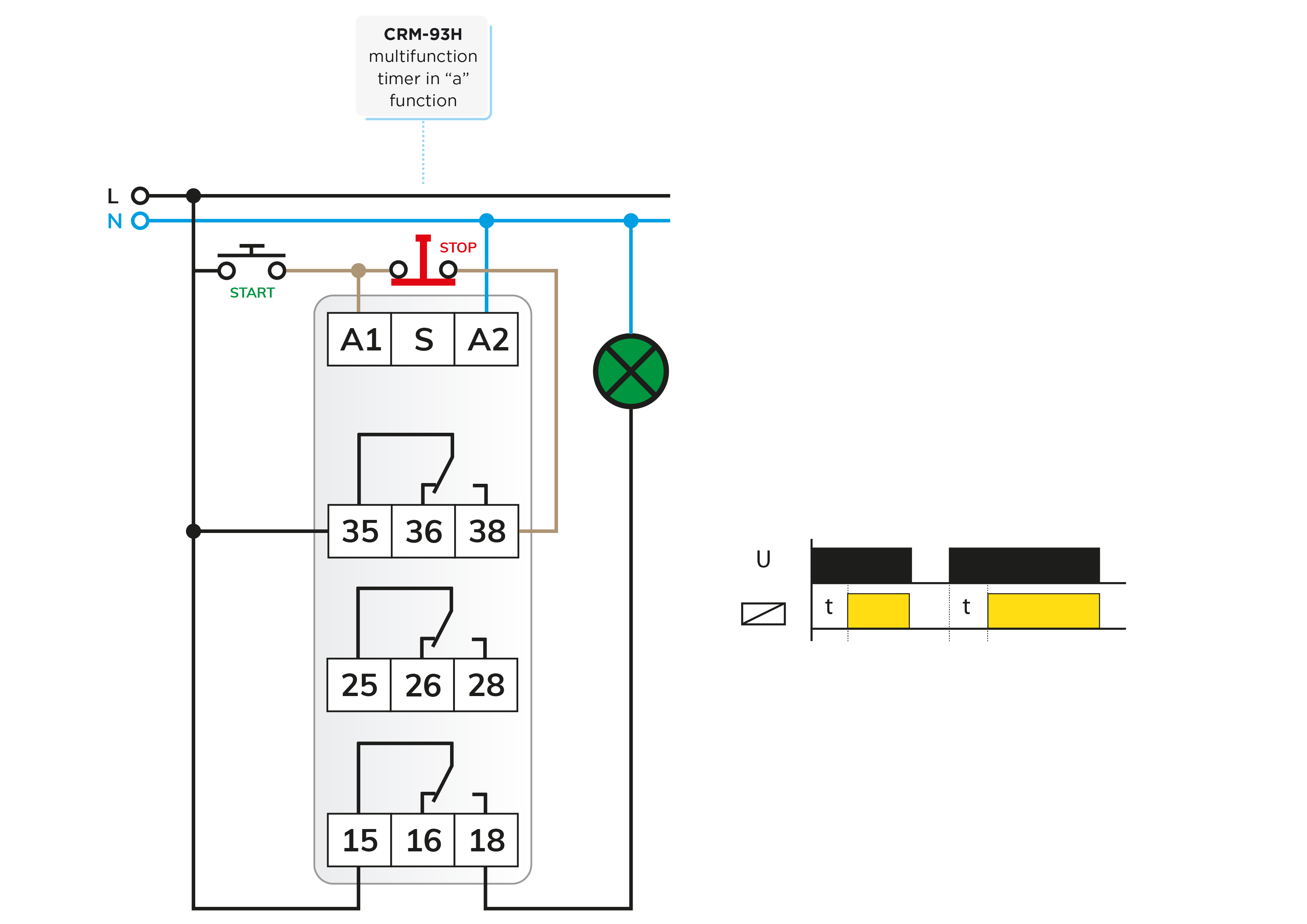
The CRM-2T time relay, originally designed as a star/delta controller for motors, can also serve the same purpose. Channel 1 can function as the timer for long presses (adjustable for up to 100 days!) and is self-sustaining, while channel 2 can be utilized to switch the consumer, even from another power supply.
Though not illustrated, the wiring logic is evident from the wiring diagrams provided in the downloadable descriptions.
In previous setups, a separate STOP button was necessary to turn off the consumer. The circuit depicted in Figure 3 enables turning the consumer on with a long press of a button and turning it off with a long press of the same button.
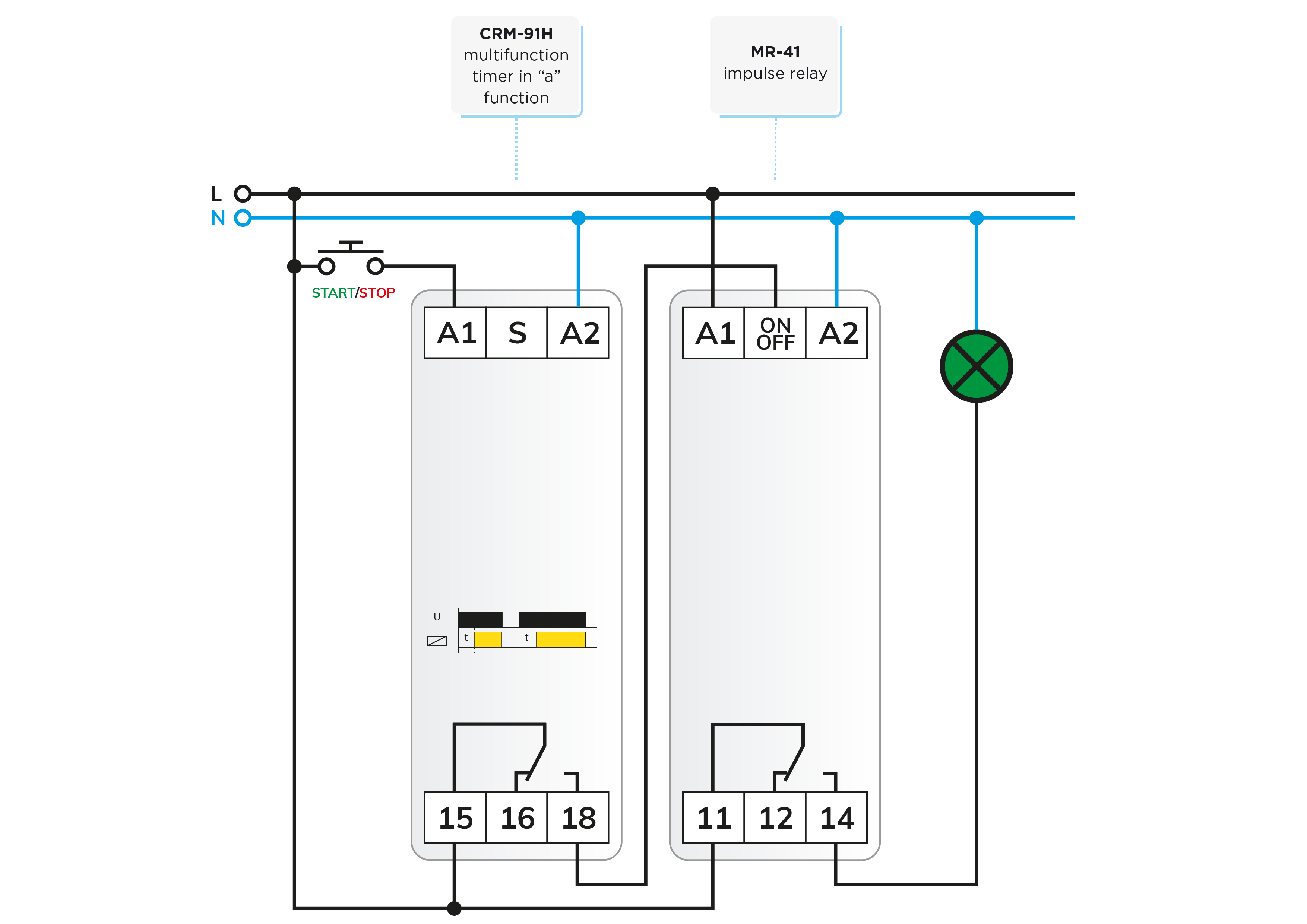
With this solution, we also require the MR-41 pulse relay to retain the current status. This relay alters the status of its output relay each time a button is pressed, turning the consumer on or off. The MR-41 reacts to the rising edge of the control signal received at the ON/OFF input. As soon as the delay elapses and the output of the time relay is activated, the pulse relay promptly switches."
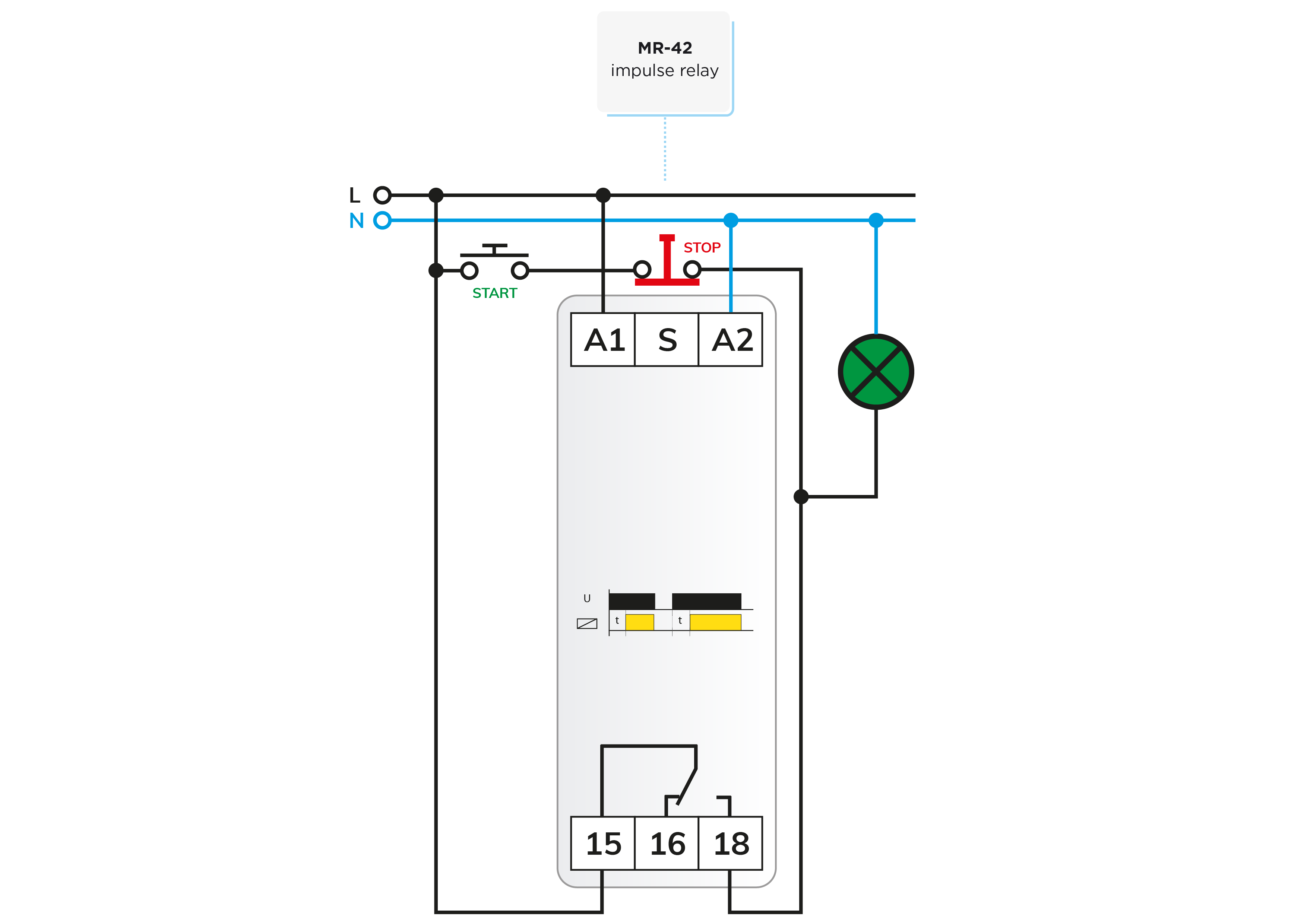
In some applications, alongside a long-press switch-on function, there might be a need to switch off with a short press of the button. Figure 4 illustrates a circuit solution for such a scenario.

Pressing the button while the consumer is switched on results in an immediate switch-off. To achieve this, the pushbutton signal is only applied to the ON/OFF input of the pulse relay if the output of the pulse relay is activated. In other words, the next time the button is pressed, the consumer must be immediately switched off. For this purpose, we utilize the MR-42 two-relay output pulse relay.
The MR-42 essentially functions as a "stepping" relay, but by connecting terminals B1 to B2, the two relays operate in parallel (similar to an MR-41 but with two outputs). One output controls the consumer, while the other directs the pushbutton signal to the ON/OFF input. This arrangement allows the pulse relay to be activated or deactivated with a single press of the button.
The time relay operates as usual - a long press activates the outputs of the pulse relay, including the consumer, while switching the pushbutton signal to the ON/OFF input.
While the pushbutton is held down, the ON/OFF input receives power simultaneously from terminal 18 of the time relay and directly from the pushbutton. This ensures that after activation, the pulse relay cannot be reactivated due to the closed pushbutton until it is released and pressed again.
If the pulse relay is activated and the button is pressed, the pushbutton immediately triggers the pulse relay due to the direct connection, regardless of whether the time relay is also activated and begins its timing.
Thus, a short press of the button immediately switches off the consumer. However, it does not matter if the button is not released and remains pressed for an extended period, as the time relay's output to the ON/OFF input cannot generate another rising edge control signal while the button is held down."
Attention! The solutions presented in the articles are illustrated with conceptual circuit diagrams in which, despite repeated inspections or tests under workshop conditions, errors may occur. It is the installer's task and responsibility to check their suitability for a given task and to make any changes! The author and the company do not accept any liability for damages or other problems resulting from the use of the presented solutions. The colors of the wires in the drawings only help for easier transparency, they do not necessarily match the colors of the standard wiring!

 E-shop